This video shows how to configure a failover IPSec VPN between PA-850 firewall and AWS. Assuming the AWS has configured their IPSec VPN and sent the configuration file to you. Here are the steps:
Step 1: Configure Tunnel
Step 2: Create IKE Crypto Profile
Step 3: Configure IKE Gateway
Step 4: Configure IPSec Crypto
Step 5: Configure IPSec Tunnel
Step 6: Configure Virtual Router
Step 7: configure Security and Policy Rules
Step 8: Create a tunnel monitor for failover
Step 9: Commit the configuration and test
Step 1: Configure Tunnel
AWS configuration
edit network interface tunnel units tunnel.1
set ip 169.x.x.26/30
set mtu 1427
On PA-850
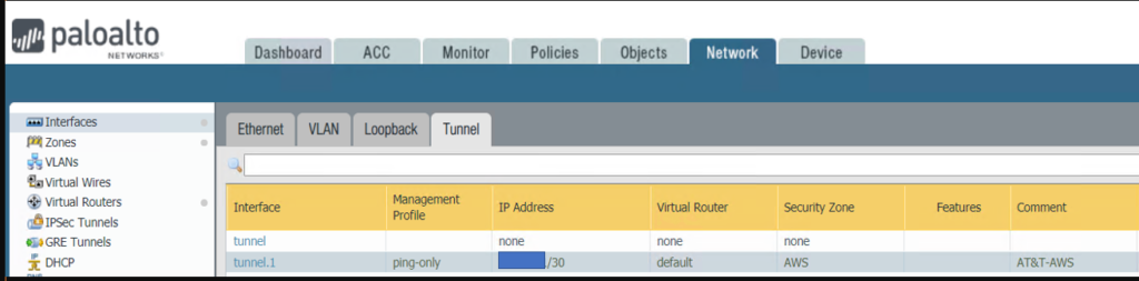
1. With Paloalto web utility open, Go to Network >Interface > Tunnel tab.
2. Click Add to create a new tunnel interface.
3. Enter the following parameters:
* Name: tunnel.1
•Virtual router: (select the virtual router you would like your tunnel interface to reside)
•Click OK to save the settings.
* Re-open Tunnel.1
* Create a new Security Zone. Or you can create the zone in Network>Zones
•Enter Zone name, for example AWS
•Click on Add under Interface
•Select the Tunnel.1 which you just created.
* Click OK to save the settings.
•We need to configure ip-address since we intend to run dynamic routing protocols over the tunnel interface. However, if the Tunnel interface is in the zone where the traffic run Static Routing, configuring ip-address on the tunnel interface is optional
•To configure IP Address, click on IPv4 tab.
•Click Add
•Entre the public IP address for connecting to AWS.
* You may want to create a Management Profile, PING-Only in our example
* The Tunnel.1 setting looks like this
Step 2: Create IKE Crypto Profile
AWS configuration
configure
edit network ike crypto-profiles ike-crypto-profiles vpn-xxxx-0
set dh-group group2
set hash sha1
set lifetime seconds 28800
set encryption aes-128-cbc
On PA-850
•Go to Network>Network Profiles>IKE Crypto.
•Click Add
* Enter the IKE Crypto profile (IKEv1 Phase-1) parameters, which should match on the remote firewall for the IKE Phase-1 negotiation to be successful.
Step 3: Configure IKE Gateway
AWS Configuration
edit network ike gateway ike-vpn-xxxx-0
set protocol ikev1 ike-crypto-profile vpn-xxxx-0 exchange-mode main
set protocol ikev1 dpd interval 10 retry 3 enable yes
set authentication pre-shared-key key xxxx
set local-address ip 12.x.x.130
set local-address interface ethernet1/1
set peer-address ip 52.x.x.251
On PA-850
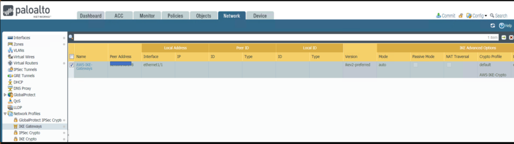
•Go to Network>Network Profiles>IKE Gateway.
•Click on Add to configure the IKE Phase-1 Gateway.
* Enter these local and peer IP addresses and info to match AWS configuration.
•Click on Advanced Options
* The IKE Gateway configuration looks like this
Step 4: Configure IPSec Crypto
AWS Configuration
edit network ike crypto-profiles ipsec-crypto-profiles ipsec-vpn-xxxx-0
set esp authentication sha1
set esp encryption aes-128-cbc
set dh-group group2 lifetime seconds 3600
On PA-850
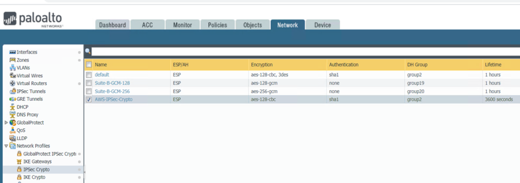
* Go to Network>Network Profiles>IPSec Crypto
* Click Add to create a new Profile
•Configure the IPSec Crypto profile to specify protocols and algorithms for identification, authentication, and encryption in VPN tunnels based on IPSec SA negotiation (IKEv1 Phase-2), which should match AWS configuration
* IPSec Crypto Profile looks like this
Step 5: Configure IPSec Tunnel
AWS Configuration
set zone untrust network layer3 tunnel.1
On PA-850
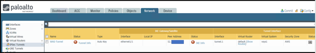
•Go to Network>IPSec Tunnels.
•Click Add to create a new IPSec Tunnel.
* In the General window select the Tunnel Interface, the IKE Gateway and IPSec Crypto Profile you just created above to set up the parameters to establish IPSec VPN tunnels between firewalls.
* IPSec Tunnel configuration looks like this
Step 6: Configure Virtual Router
AWS Configuration
set network virtual-router default interface tunnel.1
edit network tunnel ipsec ipsec-tunnel-1
set auto-key ipsec-crypto-profile ipsec-vpn-xxxx-0
set auto-key ike-gateway ike-vpn-xxxx-0
set tunnel-interface tunnel.1
set anti-replay yes
On PA-850
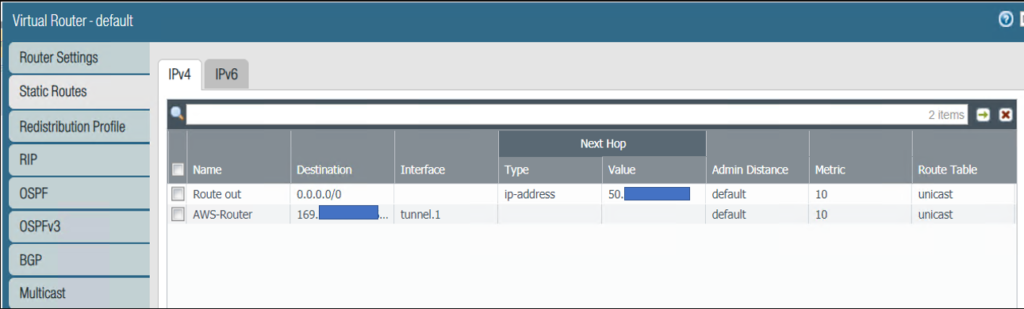
* Go to Network>Virtual Routers.
* Click on your Virtual router profile
* Click Static Routes and then Add to add a new route for the network that is behind the other VPN endpoint
•Be sure to use the proper Tunnel Interface.
•Note: If we configure failover, the Metric # should be bigger for example the first tunnel is 10 and second tunnel Metric is 20.
•Virtual Router configuration looks like this
Step 7: configure Security and Policy Rules
AWS Configuration
edit rulebase pbf rules pbf-vpn-vpn-xxxx-0
set action forward nexthop ip-address 169.x.x.25
set action forward egress-interface tunnel.1
set action forward monitor profile tunnelmonitor disable-if-unreachable yes ip-address 169.x.x.25
set source LAN-CIDR source-user any destination VPC-CIDR application any service any
set from zone trust
set disabled no
On PA-850
* By default the ike negotiation and ipsec/esp packets would be allowed via the intrazone default allow.
If you wish to have more granular control, you could specifically allow the required traffic and deny the rest.
Step 8: Create a tunnel monitor for failover
AWS Configuration
edit network profiles monitor-profile tunnelmonitor
set interval 2 threshold 5 action fail-over
On PA-850
•Repeat above 1 to 7 steps to create a second IPSec Tunnel with different parameters.
•Go to Network>Virtual Routes
•Select the default
•Click on Static Routes
•Select the Route we configured before, Route to AWS in our example
•Check Path Monitoring, and enter info based on AWS configuration
•Note 1: you configure Path Monitoring on the first IPSec tunnel only Note: Destination IP is Tunnel Interface next Hop IP, 169.x.x.25 (169.x.x.26/40)
* Go to Network>IPSec
Tunnels
* Select each Tunnel
* Check the first Tunnel Monitor
* Enter the destination IP 169.x.x.25 in our example
* Go to the second tunnel’ Monitor, enter destination IP 169.x.x.223 in our
example
* Click OK to save the settings.
Step 9: Commit the configuration and test
To check the IPSec Status, go to Network>IPSec Tunnels
Or ping other side IP address for example ping 10.60.3.12
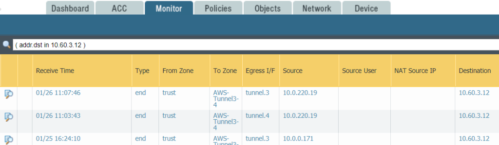
And check the Monitor
To test failover, you can change the first tunnel monitor IP address, for example 169.x.x.25 to 169.x.x.1 which is not a good Ip address so that the Tunnel 1 status is red and not available. The ping other side IP address. You can check the monitor to find which tunnel issuing.
In below example, we ping other side IP 10.60.3.12 using tunnel3. After the Tunnel3 doesn’t work, we can ping 10.60.3.12 using Tunnel4. Then we use Tunnel3 fix the problem.
Please view this step by step video: