Run resmon.exe to open Resource Monitor.
You have option to check Overview, CPU, Memory, Disk and Network.
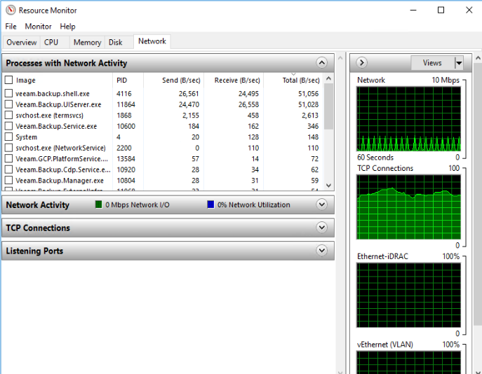
Under CPU, you have these options: Processes, Services, Associated handles, and Associated Modules.
Under
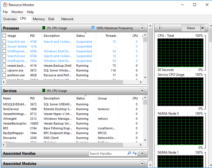
Run resmon.exe to open Resource Monitor.
You have option to check Overview, CPU, Memory, Disk and Network.
Under CPU, you have these options: Processes, Services, Associated handles, and Associated Modules.
Under
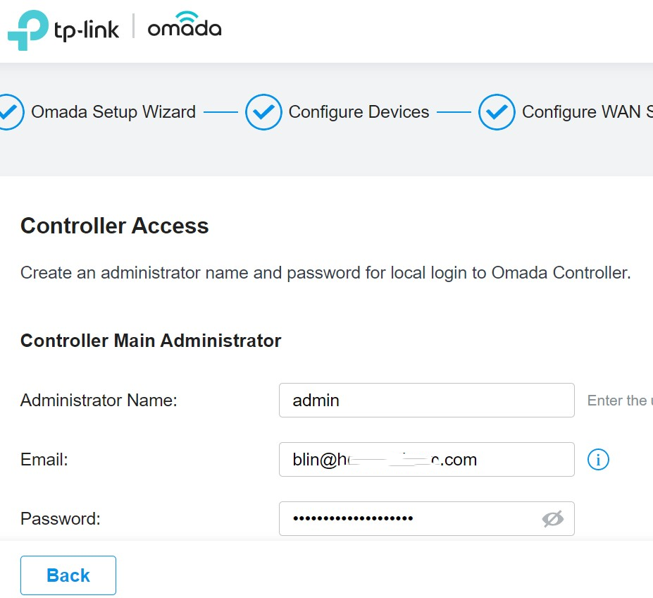
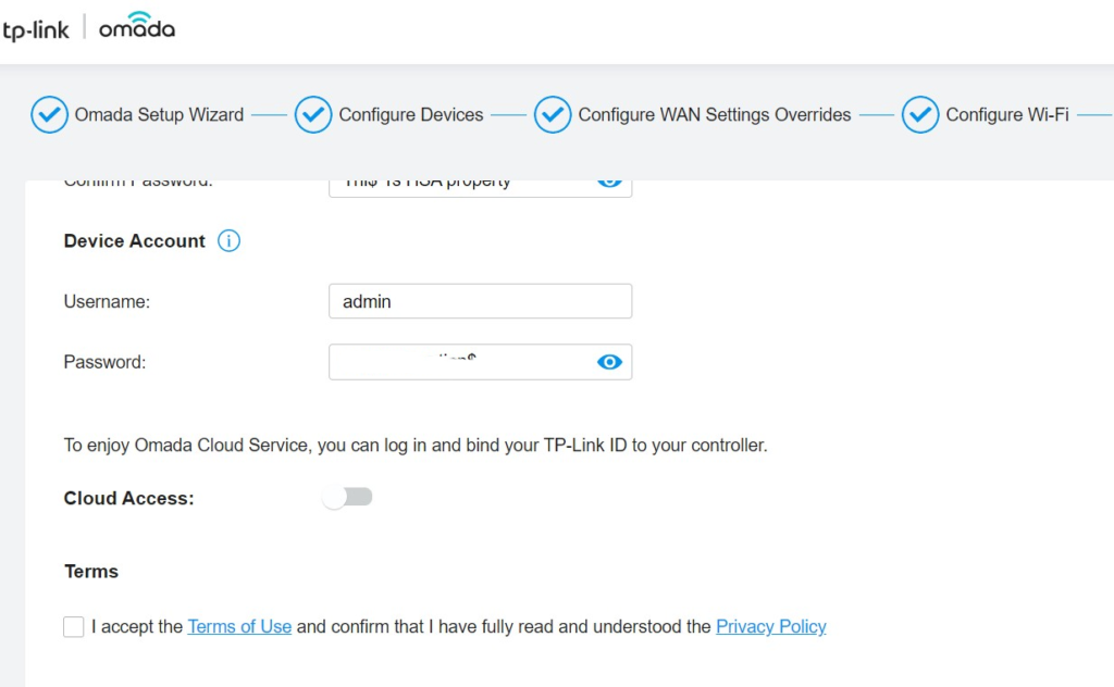
3. Enter the Controller Access Administrator Name, email address, Password.
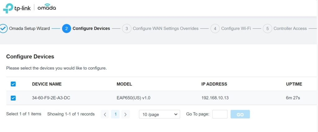
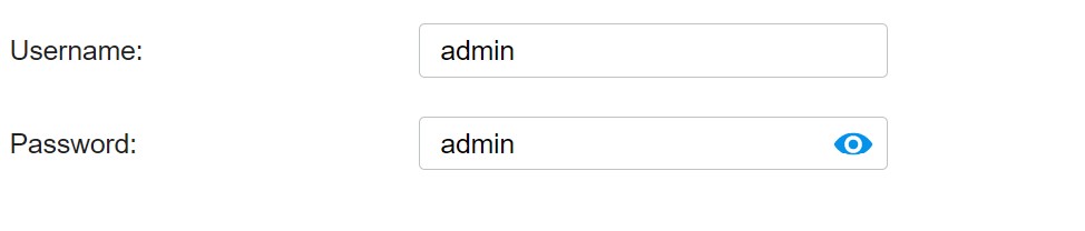
4. Enter the Device Account Username and Password. By the default the username and password are admin.
5. Configure WAN Settings Overrides.
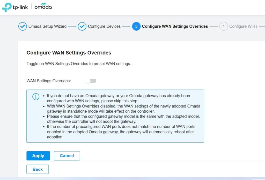
6. Configure WAN Settings
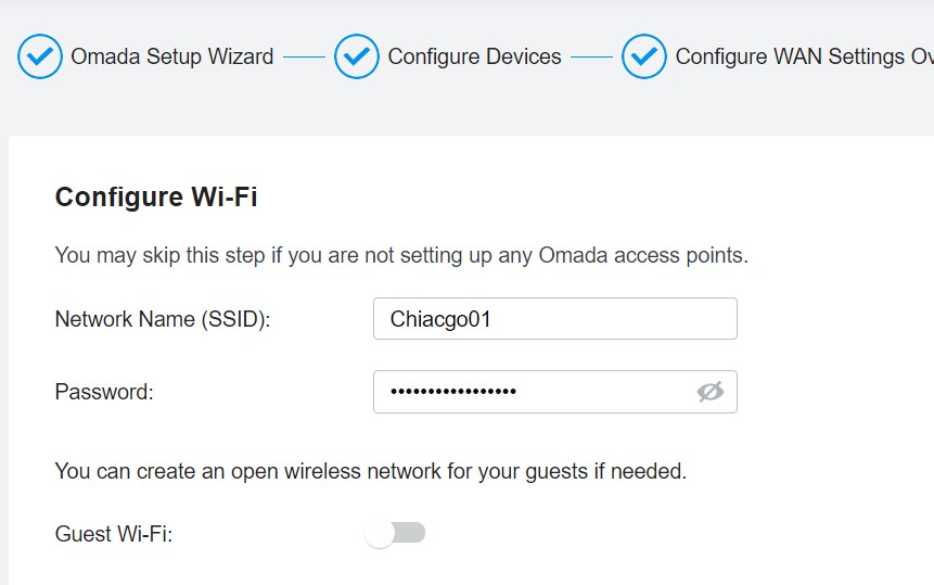
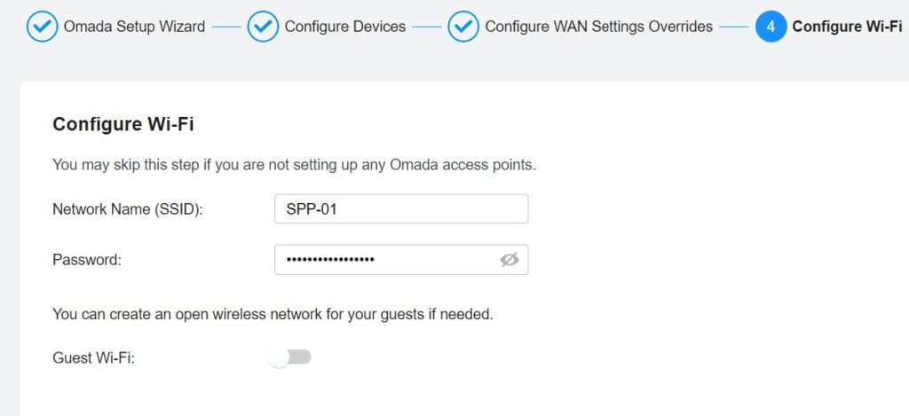
7. Configure Wi-Fi Controller Access.
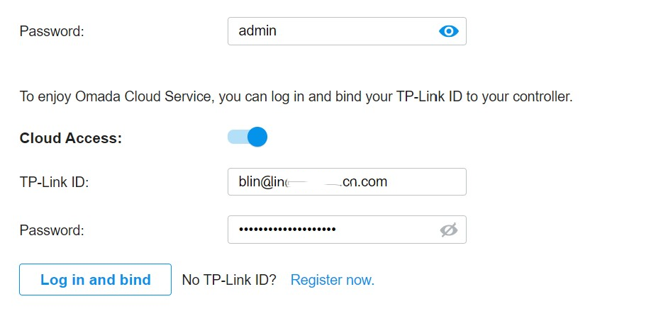
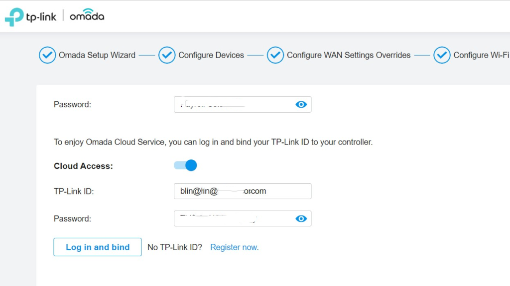
8. Enable Omada Cloud Service.

9. Configure Wi-Fi Controller network name (SSID)
10. Enter Device Account Username and Password.
11. Configure Cloud Access
12. complete the settings.
Please view this step by step video:
Step 1: Download and install Omada Software Controller
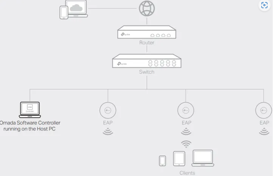
Step 2: Download and install the TP-Link Omada App on your mobile device. It can be downloaded from App Store or Google Play:

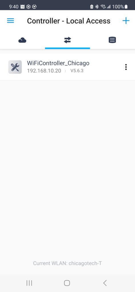
Step 3: Connect your mobile device to the EAP
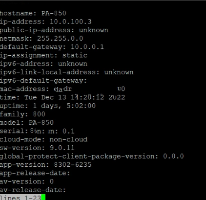
Q: We would like to enable MFA on our PA 850. However, I don’t see the options.
A: You may integrate the firewall with MFA vendors through RADIUS or vendor APIs such as DUO, Radius, Ping, Microsoft Azure MFA, Ping-ID, SecurID, Okta, and RSA.
Please refer to these articles.
PAN-OS Administrator’s Guide – Configure Multi-Factor Authentication
Palo Alto Networks Compatibility Matrix – MFA Vendor Support
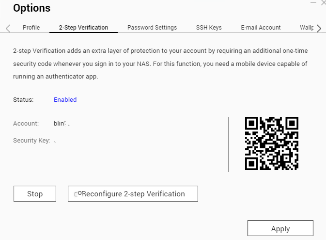
The 2-step verification, also known as Two-factor authentication, is a security feature that requires two forms of authentication to access QNAP NAS. By default, MFA on QNAP is optional. This article shows how to enable it step by step.
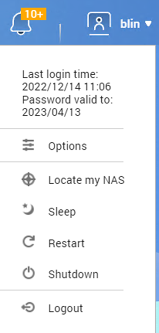
3. Click on 2-step verification.
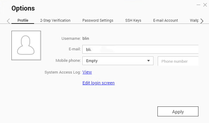
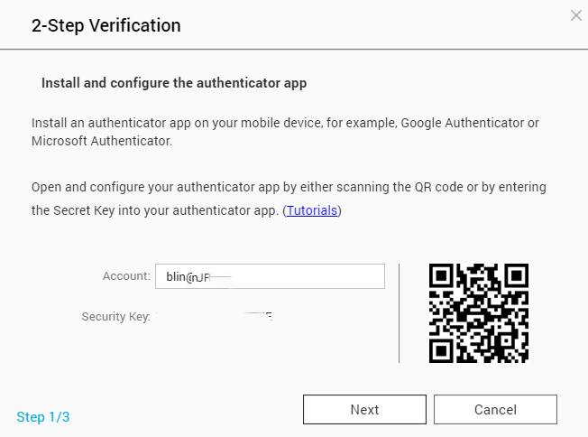
4. Use your phone to scan the QR code.
5. On the Authenticator app (Google or Microsoft Authentication app), it should display a sequence of 6 digits, which should be input on the security code box, after clicking in “Next” button, please, refer to the picture below showing what should be displayed on the screen.
6. After “Verify”, click on the Next button to finalize the setup of the 2-step verification. You will be requested to setup a security question or an email, to have an alternative method of authentication, in case you have no access to your phone.
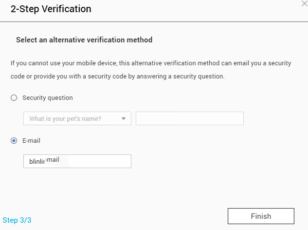
7. After clicking on Finish, a warning popup remind you to log out.
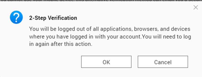
8. When you login QNAP next time,
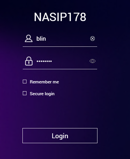
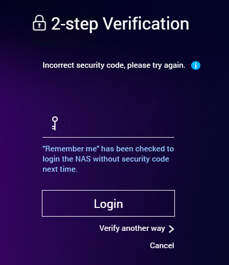
9. The second step will be the requested security code showed on the authenticator app that you have chosen to use for this purpose.
Please view this step by step video
Multi-factor authentication (MFA), also known as two-factor authentication, is a security feature that requires two forms of authentication to access Barracuda Cloud Control. By default, MFA is optional. The account administrator can specify whether MFA is required for all users or for himself on a Barracuda Cloud Control account. This article shows how to do so.
To enable MFA for an administrator, log into Barracuda Cloud Control as the administrator on the account: https://login.barracuda.com/
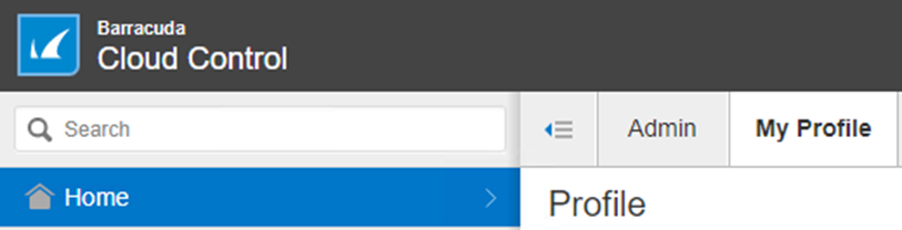
go to Home > My Profile
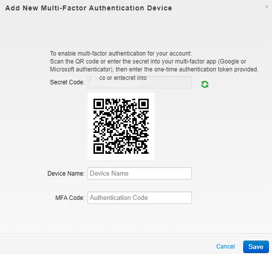
Under Multi-Factor Authentication, click on Add New Device
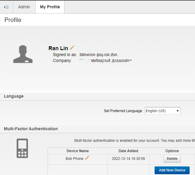
Scan the QR code using your phone and enter the code you receive from Google or Microsoft Authentication. Click Save.
To enable MFA for all users, please follow these steps.
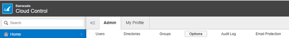
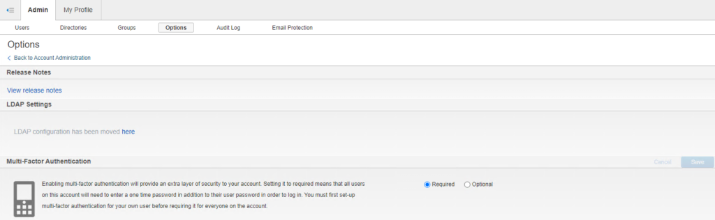
Go to the Home > Admin > Options page
Under Multi-Factor Authentication, check Required and then Save.
Now, test it.
Please view this step by step video:
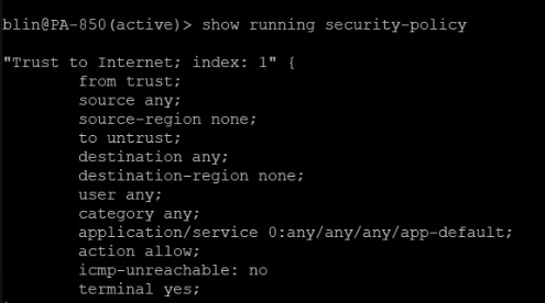
2. >show running security-policy – Show the running security policy.
3. > request restart system – Restart the device.
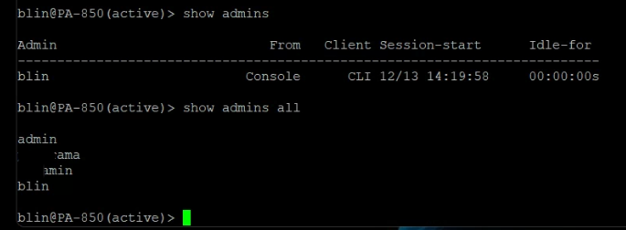
4. > show admins – Show the administrators who are currently logged in to the web interface, CLI, or API.
5. >show admins all –
Show the administrators who can access the web interface, CLI, or API, regardless of whether those administrators are currently logged in.
When you run this command on the firewall, the output includes both local administrators and those pushed from a Panorama template.
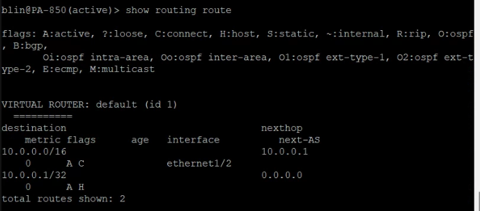
6. >show routing route – Display the routing table
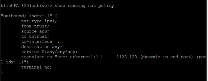
7. >show running nat-policy – Show the NAT policy table
8. > show vpn flow – Show IPSec counters
9. >show vpn gateway – Show a list of all IPSec gateways and their configurations
10. >show vpn tunnel – Show a list of auto-key IPSec tunnel configurations
11. >ping host <destination-ip-address> – Ping from the management (MGT) interface to a destination IP address
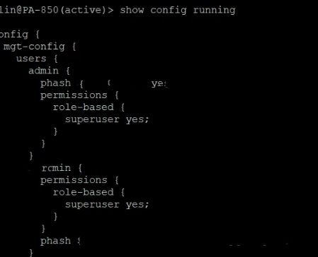
12. >show config running – display configuration
13. Show users
For example
show user group name cn=vpn,cn=users,dc=chicagotech,dc=net
short name: chicagotech\vpn
source type: ldap
source: Chicagotech-Groups
[1 ] chicagotech\blin
[2 ] chicagotech\msmith
[3 ] payroll\sgarcia
[4 ] payroll\test1
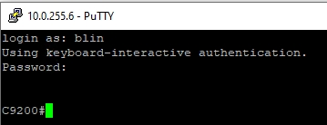
This article shows you a step-by-step procedure to backup and restore a configuration from/to a Cisco router or switch to a TFTP server. Before you proceed, make sure you have a TFTP server on the network to which you have IP connectivity.
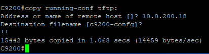
2. Copy this configuration file to the TFTP server:
Switch#copy running-config tftp:
Press Enter and Enter to process the backup.
To restore, run this command:
Switch#copy tftp: running-config
Address or name of remote host []? 10.0.200.18
Source filename []? C9200-config
Destination filename [running-config]?
To upgrade the C9000 Switch in install mode please follow the next steps:
1. Configure #install remove inactive
2. Copy the .bin image you want to upgrade to, into the flash. You can do this with a usb or via tftp
a. USB way: # copy usbflash0:(image-name.bin) flash:
b. TFTP way: # copy tftp: flash:
i. Then fill in the required information such as host and file name (image-name.bin)
3. Set the boot variable to the correct one. This should be packages.conf. Issue the following commands:
a. >enable
b. #conf t
c. (conf)#no boot sys
d. (conf)#boot sys flash:packages.conf
e. (conf)#do wr <<<<<< Very important to save configuration changes
4. Return to the privileged mode
a. (config)# end
5. Start the install process (Will ask to reload once the .pkg files finish to be generated)
a. # install add file flash:(image-name.bin) activate commit
6. After reload the install process its finished and just verify that the desired version is installed.
# show version
To upgrade the C9000 Switch in Bundle Mode please follow the next steps:
Switch>enable
Switch# copy [tftp|usb] flash: transfer files to the flash: of the device via the desired method tftp server or usb
Switch# dir flash:*.bin
Switch#verify /md5 flash:[IOS-XE.bin] – Please verify MD5 signature to avoid a corrupt IOS image
Switch#configure terminal
Enter configuration commands, one per line. End with CNTL/Z.
Switch(config)#no boot system
Switch(config)#boot system flash:[IOS image]
Switch(config)#end
Switch#write memory
Switch#show run | inc boot system
boot system flash: [IOS image] – it will display currently selected boot image
Switch#show boot
reload